


Details Explanation
YSIQ(D)50seriesGas/electric intelligent three-wayregulating valveIt is a national Torch Plan project in 2010 and holds multiple national patents. The valve adopts a modular design with strong universality and interchangeability, and has a compact structure. A sleeve guide valve core with a balanced piston, using piston sealing rings of different materials to achieve pressure balance characteristics, suitable for various high-pressure differential situations, and meets the user's usage requirements. The compression type connection between the valve seat and the valve body effectively improves the sealing level and stability of the valve, and is extremely convenient to use and maintain, thereby greatly improving the comprehensive performance of the regulating valve.
YSIQ50 series pneumatic intelligent three-way regulating valve is equipped with ZM10 type multi spring high-strength actuator and intelligent valve positioner; YSID50 series electric intelligent three-way regulating valve is equipped with an intelligent electric actuator.
The ZM10 type multi spring high-strength actuator adopts a modular design, which allows for easy replacement of positive and negative action forms on site, and provides effective anti-corrosion protection for the spring, thereby extending the service life of the actuator and facilitating user use. The matching of the actuator and intelligent electrical valve positioner adopts a design without pipeline connection, which improves the seismic performance, stability and adjustment accuracy of the regulating valve, and meets the precise adjustment of working conditions.
This series of products comes in various types such as standard, heat dissipation, and corrugated tube sealing. The nominal pressure rating of the product includes PN (MPa) 1.6, 2.5, 4.0, 6.4, 10.0 (150lb, 300lb, 600lb); Valve body diameter range DN (mm) 25-250 (1 "-10"); Suitable for various grades within the fluid temperature range of -40 to+450 ℃; Leakage level: Level IV; The flow characteristics include straight lines and equal percentages. Multiple varieties and specifications are available for selection.
Working principle
Pneumatic YSIQ50:
The locator receives standard current signals or computer signals, converts them into valve position set values, and converts the linear displacement of the actuator into angular displacement through a connecting device, which is measured by a position sensor and fed back to the microprocessor.
The microprocessor compares the actual valve position feedback value with the set value, detects the deviation, and outputs a pulse width modulation command (PWM) to the piezoelectric valve based on the magnitude and direction of the deviation. The piezoelectric valve adjusts the intake or exhaust volume of the diaphragm head according to the control command.
Electric YSID50:
After A/D conversion, the standard current signal or computer signal enters the intelligent signal acquisition and control unit of the intelligent electric actuator.
The signal acquisition control unit constantly detects the input signal and position feedback signal. When the two signals are unbalanced, it outputs a pulse width modulation command (PWM) to the bidirectional thyristor based on the magnitude and direction of the deviation, making it conductive and driving the motor to operate in the direction of reducing the deviation, thereby driving the deceleration mechanism and changing the opening of the valve.
control model
The control mode adopts PWM (Puise Width Modulation) drive;
Full speed state: When the control deviation is large, output a continuous signal;
Medium speed state: When the deviation is not significant, output a pulse signal;
Slow fine-tuning: When the deviation is small, output a smaller pulse signal;
Maintain positioning: When the deviation is small enough within the range of valve adjustment accuracy, there is no control command output.
Structural diagram

Common materials for main components
| Serial Number | Part name | Common materials | ||||
| 1 | Valve body | WCB | WC6 | CF8 | CF8M | |
| 2 | Valve seat | 304, 316+overlay welding with Stellite alloy | 316+welded Stellite alloy | |||
| 3 | Valve core | hard seal | 304, 316+overlay welding with Stellite alloy | 316+welded Stellite alloy | ||
| soft seal | 304, 316+PTFE | 316+PTFE | ||||
| 4 | Valve cage | 304, 316 | 316 | |||
| 5 | Guide Sleeve | 304, 316 | 316 | |||
| 6 | Valve stem | 304, 316 | 316 | |||
| 7 | Valve cover | WCB | WC6 | CF8 | CF8M | |
| 8 | Balance piston | HT200、Al | ||||
| 9 | Balance piston ring | Fluororubber, stainless steel+reinforced polytetrafluoroethylene, flexible graphite ring | ||||
*The above are commonly used materials, and the specific grades are subject to the order contract.
Specifications and technical parameters
| Form | Three way pressure balance type |
| Nominal Diameter | DN25~DN250(1”~10”) |
| nominal pressure | PN16、25、40、64、100(150lb、300lb、600lb) |
| Inherent flow characteristics | Equal percentage, straight line |
| Inherent adjustable ratio | 50﹕1 |
| Upper valve cover form | Standard type: Cast steel: -20~200 Cast stainless steel:- 40~200 |
| Heat dissipation type: cast steel: -29~425 cast stainless steel:- 40~450 | |
| Valve seat leakage | Grade IV, V (please confirm with the technical department), VI (quick opening cutting type, soft seal) |
Traffic characteristics
| Valve seat diameter dn (mm) | 25 | 32 | 40 | 50 | 65 | 80 | 100 | 125 | 150 | 200 | 250 |
| Flow coefficient Kv | 8.5 | 13 | 21 | 34 | 53 | 85 | 135 | 210 | 340 | 535 | 800 |
The direction of fluid flow

Note: The fault location is defined by the position of the main valve core (horizontal passage).
Main performance indicators
| Serial Number | project | Standard intelligent valve | Heat dissipation, low-temperature intelligent valve |
| 1 | Basic error<(%) | ±1 | ±2.5 |
| 2 | Return difference<(%) | 1 | 2.5 |
| 3 | Dead zone<(%) | 0.4 | 1 |
| 4 | Constant point deviation<(%) | ±1 | ±2.5 |
| 5 | Rated travel deviation < (%) | +2.5 | +2.5 |
Note: The performance indicators of this product are higher than GB/T4213-2008.
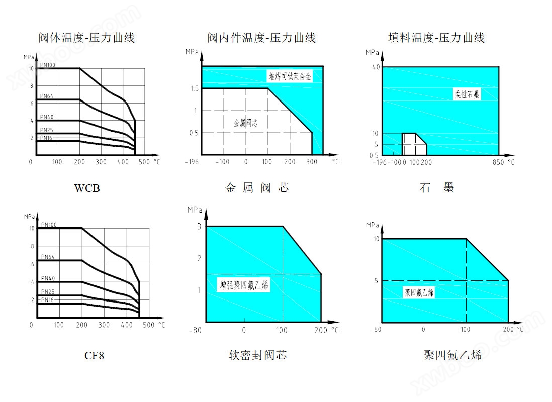
The operating temperature and pressure range of valve body, valve internals, and packing materials
Technical parameters of the executing mechanism
The ZM10 series pneumatic multi spring actuator adopts a modular design, so it only needs to be disassembled and assembled locally to achieve the conversion between the two modes of action of air opening and air closing. The gas path connection between the actuator and the valve positioner adopts an internal connection combination, and the gas discharged from the positioner can be injected into one side of the spring chamber to generate a pressure slightly higher than the atmospheric pressure of the external environment, so as to prevent corrosive gases from the external environment from being sucked in and corroding the spring and other components.

Gas Open (FC): When the gas source fails, the actuator spring closes the valve.
| model | Membrane area (cm)2) | Number of springs | Travel distance (mm) | Spring range (KPa) | Thrust (KN) |
| ZM10-1 | 210 | 3 | 20 | 75 ~ 150 | 1.6 |
| 6 | 150 ~ 300 | 3.2 | |||
| ZM10-2 | 320 | 3 | 30 | 75 ~ 150 | 2.4 |
| 6 | 150 ~ 300 | 4.8 | |||
| ZM10-3 | 720 | 3 | 60 | 75 ~ 150 | 5 |
| 6 | 150 ~ 300 | 10 | |||
| 9 | 180 ~ 370 | 13 | |||
| 12 | 220 ~ 440 | 16 |
Air shut-off (FO): When the air source fails, the actuator spring opens the valve.
| model |
Membrane area (cm2) |
Number of springs |
trip (mm) |
Spring range (KPa) | Thrust (KN) Gas supply pressure (MPa) | ||||
| 0.2 | 0.3 | 0.4 | 0.5 | 0.6 | |||||
| ZM10-1 | 210 | 3 | 20 | 75 ~ 150 | 1.0 | 3.2 | 5.2 | 7.2 | 9.4 |
| 6 | 150 ~ 300 | – | – | 2.1 | 4.2 | 6.3 | |||
| ZM10-2 | 320 | 3 | 30 | 75 ~ 150 | 1.6 | 4.8 | 8.0 | 11.2 | 14.4 |
| 6 | 150 ~ 300 | – | – | 3.2 | 6.4 | 9.6 | |||
| ZM10-3 | 720 | 3 | 60 | 75 ~ 150 | 3.6 | 10.8 | 18.0 | 25.2 | 32.4 |
| 6 | 150 ~ 300 | – | – | 7.2 | 14.4 | 21.6 | |||
Traffic characteristics

Table 8 Relative flow values of various inherent flow characteristics under relative stroke R50 Unit:%
|
L/Lmax Q/Qmax characteristic |
0 | 10 | 20 | 30 | 40 | 50 | 60 | 70 | 80 | 90 | 100 |
| Straight Line | 2 | 11.8 | 21.6 | 31.4 | 41.2 | 51 | 60.8 | 70.6 | 80.4 | 90.2 | 100 |
| Equal percentage | 2 | 3 | 4.37 | 6.5 | 9.6 | 14.1 | 20.9 | 30.9 | 45.7 | 67.6 | 100 |
Annotation on allowable differential pressure gauge
The filler material is PTFE; Values are limited by nominal pressure and pressure temperature charts;
The flow direction of the medium is opposite to the direction in which the valve core closes; Bellows sealing class P2When ≠ 0, it needs to be rechecked.
The leakage level of metal sealed type is level IV;
special requirements
Special inspection; Used under vacuum conditions;
Complete oil and water removal treatment; Special media (such as oxygen);
Copper prohibition treatment; Use stainless steel connectors;
Special interface; Specify the coating color.
Connection size and standard
Connection method: flange; Threads, welding (to be specified by the user)
Flange standard: 150lb~600lb steel flange according to HG/T20615-2009
PN16~100 steel flange according to HG/T20592-2009
Sealing surface form: 150lb~600lb, PN16 is a protruding surface (RF);
PN40、 63 and 100 are concave convex surfaces (MFM), and the valve body is concave (FM);
Structural length: ASME B16.10、 GB/T17213、 GB/T12221、
Valve design and manufacturing standards: GB/T4213、GB/T17213、JB/T7387、IEC60534、ISA75.01
Valve leakage standard: GB/T4213、JB/T7387、IEC60534-4、ANSI/FCI70-2
The connection method, valve body flange, and structural length can be manufactured according to the standards specified by the user. For example: GOST, DIN, JIS, etc.