
VIP member

T968Y electric regulating valve
Caliber range: DN50-300mm Pressure range: PN1.6-6.4MPa Applicable temperature: 450 ℃ Product application: T968Y series heating water level drain regul
Product details
-
T968Yelectriccontrol valve
1、 Product Details
Product model: T968Y
Product Name: Electric Control Valve
Electric(T968Y)In order to improve the economy of power plants, steam turbines are equipped with regenerative systems, which include high and low pressure heaters. To ensure that the heater operates with a water level and prevent the extraction of steam from the previous stage of the turbine from entering the next stage when the heater operates without a water level, thereby reducing the efficiency of the turbine and the safety of the equipment, a drain control valve is installed in the drain system of the heater. It automatically opens and closes the drain control valve based on the water level signal of the heater, keeping the water level of the heater within a certain range. The working conditions of the drain control valve are very poor. In many cases, it operates in a two-phase fluid (i.e., in a mixed state of steam and water), and it operates in a throttling state. The cavitation is quite severe, and when the cavitation reaches a certain level, it cannot function as a drain control valve. In this situation, the heater cannot guarantee water level operation, which reduces the economic efficiency of the turbine operation. From this, it can be seen that choosing a drain control valve with low cavitation, low noise, simple structure, and reliable performance is particularly important. In response to the requirements of the above working conditions, our factory has researched, designed, and manufactured a new type of drain control valve. It is based on the original drain control valve and draws on foreign experience. The structure and materials have been reformed to make the valve have good working performance. Due to the use of a reasonable contact angle between the valve core and seat, there is no leakage in the closed state of the valve; The material used to manufacture the uniform flow hood and valve core is high-quality stainless steel. Even when operating in two-phase flow and throttling conditions, the cavitation speed is quite slow, which extends the service life of the valve and reduces noise. The valve design adopts a simple assembly and disassembly structure. When the internal parts are damaged, simply remove the valve cover nut to take out each part one by one and replace any part at will, making maintenance very convenient.
2、 Working principle
The T968Y series heating water level drain regulating valve consists of an electric actuator and a drain regulating valve. The input of the electric control valve is the DC electrical signal sent by the regulator, which is amplified by the servo amplifier and drives the actuator to generate axial thrust, driving the control valve to move and causing changes in the medium flow rate to regulate various parameters in the system. At the same time, the actuator sends a valve position signal for the servo amplifier to compare, so that the regulating valve always maintains a position corresponding to the input signal, completing the servo adjustment task3、 Main technical parameters
Nominal diameter DN (mm)
50
80
100
150
200
250
300
flow characteristics
Approximate linear, approximate equal percentage
Nominal pressure PN (MPa)
2.5/6.4
connection type
welding
Equipped with actuator
ZKD type
Travel L (mm)
57.6
88.2
Maximum pressure difference △ P (MPa)
0.5/3
Rated flow coefficient Cv
44
99
175
395
640
1000
1440
Working temperature t (℃)
≤450
≤450
medium
water
Note: 1. This model also includes flange type, right angle type, and flange right angle type
2. It can also be equipped with pneumatic actuators or HQ intelligent actuators
4、 Main technical performance indicators
project
Technical performance indicators
Basic error (%)
Not exceeding ± 2.5
Return difference (%)
≤1.5
Dead zone (%)
≤3
leakage
0.01% x valve rated capacity
5valveMain materials
name
material
valve body
WCB、WC6、20CrMo
valve core
316 stainless steel
shroud
17-4PH
valve stem
17-4PH
valve seat
316 stainless steel
6、 External dimensions
Nominal diameter DN (mm)
50
80
100
150
200
250
300
H(mm)
860
918
918
918
1460
1690
1690
H1(mm)
120
248
248
248
360
470
470
L(mm)
300
372
372
372
490
610
610
D1(mm)
90
150
180
200
244
355
420
D2(mm)
76
104
127
168
210
270
320
D3(mm)
50
80
100
140
180
230
270
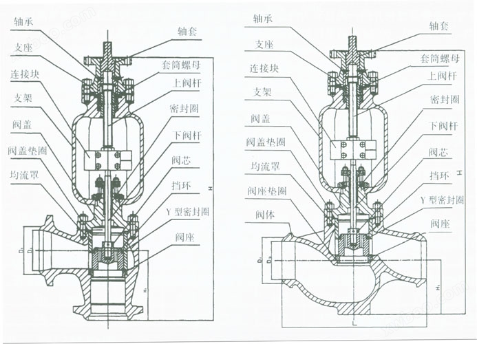
7valvestructural diagram
Online inquiry
-
Contacts
-
Company
-
Telephone
-
Email
-
WeChat
-
Verification Code
-
Message Content
-