
VIP member
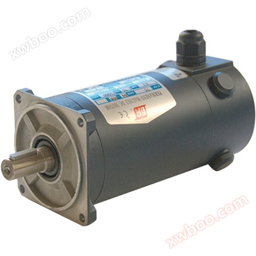
Maintenance and use of brushed motors
Instructions for use: The motor is suitable for most servo control systems and variable speed regulation control links, and is compatible with most dr
Product details
Instructions for Use
The motor is suitable for most servo control systems and variable speed regulation control links, and is compatible with most drivers. It must be noted that all parameters of the torque fed motor are within the performance requirements of the servo motor, and the specified waveform coefficients (using pure DC) should be used. When the waveform coefficient of the motor power supply exceeds the rated value, the rated value of the motor must be reduced.Before formal use, let the motor run lightly or without load for a period of time to remove some possible coating phenomena, such as the oxide film on the commutator.
Pay attention to the current and speed limits on the nameplate during operation, and do not operate at overload for a long time. Overload for 3 times should be less than 1 minute, and overload for 5 times should not exceed 5 seconds.
(1) Wiring method
There is a wiring diagram on the connection box (or wiring markings on the connectors of each motor). Note that in a closed circuit, the motor must be connected according to the polarity on the identification plate. Incorrect connections can cause motor overspeed, commutator flashover, and even demagnetization of the motor.
(2) Bearing
All servo motors use specially matched single row radial ball bearings with dual protection and permanent lubrication, which do not require maintenance under normal use conditions.
(3) Electric brush
The lifespan of electric brushes mainly depends on the load and air circulation conditions. When the air humidity is 6-12 grams of water per cubic meter, the normal wear amount after 1000 working hours is 5MM. Due to the significant impact of air humidity or circulating air pollution on the characteristics of the reversing part, even with normal load, this value will still fluctuate by about 100%.
(4) Bearing capacityThe standard structure of the shaft extension is determined by the coupling transmission, and the shaft extension only bears pure circumferential force (i.e. rated torque) without additional force. If subjected to additional force during use, the tolerance value can be consulted with our company.
Motor maintenance
(1) Daily maintenance of motorThe motor must maintain a clean environment and no water or oil should flow into the interior of the motor. The surface of the motor, especially the lead out part, should be regularly blown clean with compressed air. Regularly open the rear cover of the motor and use compressed air to blow away the carbon powder on the surface of the commutator and around the brush holder. Please note that the motor power must be cut off during any cleaning work.
(2) Replacement of Electric Brush
The replacement of electric brushes must be provided by our company's dedicated electric brushes. Before replacement, the outer surface of the motor with a diameter of 60% should be ground with sandpaper of grade 0 or above. After the circular arc surface is formed, the ground electric brush should be gently placed into the brush holder. The electric brush should slide smoothly inside the brush holder, and a slight sound of the brush hitting the commutator surface should be heard. Then, the electric brush spring should be compressed and the brush cover should be closed. After replacing the new electric brush, the motor should run without load for more than 4 hours before it can be put into normal operation.
(3) Replacement of bearings
When the bearing experiences abnormal conditions or reaches the end of its service life, it should be replaced in a timely manner. The brand of the replaced bearing should be as similar as possible to the original bearing. The disassembly of bearings should use a special die for bearings, and the assembly of bearings should use cold pressing method, and heating method is strictly prohibited. The steps for disassembling a motor are generally as follows: wiring a fan (encoder, etc.), a splash catching machine brush holder, a speed measuring machine stator, a speed measuring machine rotor, a main engine brush, a main engine rear end cover, a main engine front end cover, and a main engine stator rotor separation. Attention: When disassembling the motor, please remember the relative position between the rear end cover and the stator. When disassembling the speedometer, please remember the relative position between the brush holder and the speedometer stator.
<=''>When the commutator operates without sparks for a long time under load, a dark brown and glossy strong film layer will be formed on its surface, which can protect the commutator and reduce wear. Therefore, this oxide film must be preserved and should not be removed. If the surface of the commutator is rough, uneven, or burnt, the motor must be turned on. First, refine the surface of the commutator, then use a thin saw blade to carve mica, and finally polish the surface of the commutator with metallographic sandpaper.
Malfunctions and Corrective Methods
| Fault phenomenon |
cause of failure |
Corrective methods |
| Abnormal rotational speed |
Deviation of neutral point during commutation |
Adjust the brush holder and magnetic steel neutral point |
| Winding short circuit |
Check if the winding is short circuited |
|
| Feedback element positive feedback |
Change the wiring of the feedback component |
|
| Magnetic steel demagnetization |
Replace magnetic steel |
|
| Abnormal heating and smoking |
Long term overload |
Restore normal load |
| Short circuit of commutator or winding |
Check if the winding is short circuited, clean the commutator |
|
| Fixed rotor rubbing |
Check the air gap for debris and replace the bearing |
|
| Shell leakage |
Wiring collision shell |
rewiring |
| Carbon powder accumulation, brush holder breakdown |
Remove toner and replace brush holder |
|
| Winding and commutator breakdown to ground |
Replace the rotor |
=''>
Online inquiry
-
Contacts
-
Company
-
Telephone
-
Email
-
WeChat
-
Verification Code
-
Message Content
-