
VIP member

Heavy hammer float flap level gauge
The MS-UFZ heavy hammer float level gauge is a simple liquid level measuring instrument, which is suitable for measuring liquid levels in tanks, tanks
Product details
The MS-UFZ heavy hammer float level gauge is a simple liquid level measuring instrument, which is suitable for measuring the liquid level in tanks, oil fields, oil depots, etc. that store corrosive media in petrochemical systems, as well as in water towers (water tanks) in general enterprises and civil buildings, at a low cost. It solves the difficulty of manually measuring the liquid level. The UFZ type heavy hammer float level gauge can be used for on-site continuous measurement of liquid levels in tanks, oil fields, oil depots, and other containers in storage and transportation systems such as petrochemicals, metallurgy and power, pharmaceuticals, and papermaking. The measured media can be acidic, alkaline, high viscosity, and corrosive media. This liquid level gauge has the characteristics of simple structure, intuitive visual perception, and easy installation and maintenance
Heavy hammer float level gaugeStructural principle
Liquid level meterIt is designed based on the principle of force balance. When the liquid level is at a certain height, the weight of the float is W, the weight of the heavy hammer needle is W1, the buoyancy force experienced by the float immersed in the liquid is F, and the system friction is (. In equilibrium state: W-F-W1-f=0)
When the liquid level rises, the buoyancy force F increases, W、W1、 Both f and f remain unchanged, the balance of the above equation is disrupted, and the vertical pointer slides down. A new equilibrium is not established until the F force decreases to its original value. If the F force keeps increasing, that is, the liquid level keeps rising and the pointer keeps falling. On the contrary, if the liquid level drops, the hammer pointer rises to indicate the height of the liquid level.
Main technical parameters of MS-UFZ heavy hammer float level gauge
Measurement range: Choose freely within 0-20m
Indicator accuracy: ± 20mm
Work pressure: normal pressure or ± 200mmH20 (with V-shaped sealing tube)
Medium density: ≥ 0.6g/cm3
Installation straightness of guide wire: ≤± 5
Material: 1Cr18Ni9Ti according to the liquid part
Indicator ruler made of aluminum alloy
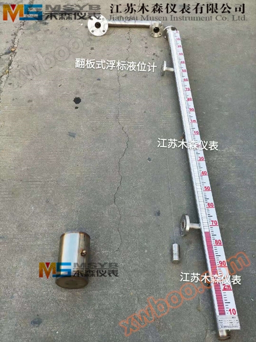
MS-UFZHeavy hammer float level gaugeInstrument structure
Heavy hammer float level gaugeIt consists of five parts: buoy, connecting wire, guide pulley, heavy hammer pointer, display ruler, etc.
1. Buoy: A buoy is made of two stainless steel (or carbon steel) hollow cones and one stainless steel (or carbon steel) hollow cylinder welded together, and guide rings are welded on both sides of the buoy to provide guidance. The function of the buoy is to directly transfer the buoyancy of the liquid level change to the steel wire, so that the steel wire can transfer the liquid level change to the hammer pointer, achieving on-site indication of the liquid level change.
2. Connecting steel wire: One end of the connecting steel wire hangs a buoy, the other end is connected to a heavy hammer pointer, and the middle part is enclosed inside the steel pipe.
3. Guiding pulley: It is designed according to the geometric shape of the on-site liquid level tank and the installation requirements of the instrument, and is composed of two parts: connecting the steel wire guiding pulley and determining the pulley housing. Its main function is to connect the steel wire guiding and reduce the resistance of the system rotation.
4. Heavy hammer pointer: It is made of A3F steel and has a pointer form in the middle. The corresponding scale value pointed by the pointer is the measured liquid level height. It moves synchronously with the change of the float and the connected steel strip.
5. Display ruler: It is made of LY11 alloy aluminum and has standard values engraved on the surface, measured in centimeters with a height of 1 meter per section.

MS-UFZHeavy hammer float level gaugeInstallation and commissioning
1. Zero adjustment of instruments
When installing the instrument, if there is no measured medium inside the tank and the float is at the bottom of the tank, the red pointed pointer of the heavy hammer should indicate the "zero" value at the top of the measuring range of the ruler, otherwise the length of the steel wire needs to be adjusted.
2. Range adjustment of instruments
On the basis of adjusting the zero position of the instrument, pull the float to the top of the container or the maximum measuring point. The red tip of the heavy hammer pointer should point to the bottom position of the scale, that is, to the maximum range point of the scale.
MS-UFZHeavy hammer float level gaugeInstallation, use and precautions
1. Installation of welding support under guide wire:
Determine the position at the bottom of the container according to the movement direction requirements of the liquid level gauge float, and weld or rivet the fixed guide wire lower support (part 1)
2. Installation of guide wire
(1) Use force to straighten the steel wire and fix it on the lower support. Be careful not to bend or knot the steel wire, so as not to affect the up and down movement of the buoy.
(2) The guiding steel wire passes through the guiding ear hook of the buoy, and then passes through the hanging hook screw (part 6) to fix the end of the steel wire and clamp it with a wire clamp, and tighten the hanging hook nut to make it in a tight state. Then tighten the upper nut to prevent loosening, and cover it with a lid.
(3) Two guide wires should be perpendicular to the ground and parallel to each other, ensuring a distance of 300mm between them
3. Ruler installation
The length of the ruler is determined based on the measurement range provided by the user at the time of ordering, and installation requires:
(1) The connecting part of the ruler should be straight, smooth, and free from any unevenness to avoid affecting the normal operation of the hammer pointer or causing measurement errors.
(2) The ruler should be perpendicular to the liquid surface inside the storage tank and should not be tilted. The verticality of the ruler installation should not exceed 5 ° to avoid the heavy hammer pointer getting stuck and causing measurement failure.
(3) When welding the ruler stand (part 11), it is advisable to ensure that the installation surface is on the same plane and the installation hole is on the same straight line as above, that is, to ensure that the scale surface of the ruler and the guide on both sides of the hammer pointer are straight, which is called a straight line, so that the hammer pointer can move up and down flexibly on the ruler.
Attention: The distance between the bipods is 1 meter.
4. Installation of buoy connecting wire and heavy hammer pointer:
One end of the buoy and the connecting steel wire is clamped and fixed with a wire clamp, and then the other end of the connecting steel wire is installed into two pre installed guide pulley boxes, connected with the heavy hammer pointer, clamped and fixed with a wire clamp, and finally adjust the guide pulley brackets so that the connecting steel wire is vertical to the horizontal, so that the buoy can move flexibly on the guide steel wire, with a sense of light slip, without jamming, twisting, knotting, winding or damage.
Attention: Master the required length of steel wire.
Ordering instructions for MS-UFZ heavy hammer float level gauge:
1. Specify the specifications and model of the liquid level gauge.
2. Measurement range L
3. The density and temperature of the measured medium and medium.
4. The installation distance and the size of the center to center distance of the bracket.
Online inquiry
-
Contacts
-
Company
-
Telephone
-
Email
-
WeChat
-
Verification Code
-
Message Content
-