
VIP member
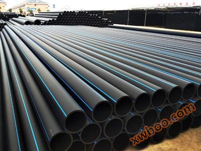
HDPE non excavation pipe
Product features: 1. Excellent construction performance, does not obstruct traffic, does not damage green vegetation, does not affect the normal life
Product details
Product Features

-
1. Excellent construction performance
Not obstructing traffic, not damaging green vegetation, not affecting the normal life and work order of shops, hospitals, schools, and residents, solving the interference of traditional excavation construction on residents' lives, and the damage and adverse effects on traffic, environment, and surrounding building foundations.
-
2. Excellent wear resistance performance
After long-term use, it has been shown that the wear resistance is more than four times that of steel pipes.
-
3. Reliable connection performance
The strength of the hot melt electric fusion interface is higher than that of the pipe body, and the joint will not break due to soil movement or live load.
-
4. Good tensile resistance
The pipeline can withstand significant drag and traction without deformation or fracture.
-
5. Suitable for more complex geological environments
High ring stiffness, good toughness, and high impact strength.
-
6. Long service life
Under rated temperature and pressure conditions, it can be safely used for more than 50 years.
Product Parameters

construction technology
HDPE non excavation pipes are generally constructed using directional drilling traction, also known as directional drilling construction, which is a technique for laying underground pipelines without excavation.

-
Pipeline inspection
PE traction pipes have strong resistance to external pressure (able to withstand large tensile forces), good flexibility (able to adapt well to settlement, strong seismic resistance), and light unit weight (can reduce friction with the hole wall during traction), making them very suitable for traction construction. To ensure the quality of the project, pipeline materials must meet various design requirements:
① The inner and outer walls of the pipeline are smooth and flat, with no cracks in the pipe body and no defects such as damage, cracks, or deformation at the pipe mouth;
② The end face of the pipeline should be flat (perpendicular to the axis of the pipeline), and there should be no obvious bending in the axial direction. The dimensions and roundness of the pipe socket outer diameter and socket inner diameter should meet the requirements;
③ The internal pressure strength and stiffness of the pipe should meet the design requirements;
-
Design of guide hole trajectory
The trajectory of the arc-shaped guide hole consists of two parts: the inclined section and the straight section. The inclined section is the transition section where the drill pipe enters the depth of the pipeline, while the straight section is the laying section where the pipeline passes through obstacles. The shape of the guide hole trajectory depends on parameters such as the starting point (point A), the ending point (point B), the depth of pipe laying (h), and the curvature radius of the inclined section (R1, R2). Among them, R1 is determined by the minimum curvature radius of the drill pipe (Rd) and the depth of pipe laying (h). According to experience, Rd ≥ 1000 d (d is the diameter of the drill pipe, 50 mm); R2 is determined by the bending radius of the applied tube.
-
Key points of segmented traction construction
The maximum length of a pipeline to be laid by traction in the project shall be determined according to the actual terrain, but shall not exceed the requirements of the design specifications. When the laying length is too long or affected by external factors such as the site, the traction machinery is insufficient to complete the pipe dragging work in one go. In this case, segmented traction construction is required (see Figure 2). After the guide hole of section AB is opened, first use the é 200 expansion head to expand it once, and then push the expansion head to the midpoint O of section AB; dig a pit at point O (2 m × 4 m × 6 m), replace the drill bit and drill along the curve until the M point is excavated, and then expand and drag the pipe in sequence to complete the laying of the AO section pipeline; Step back 23 meters and use point N as the entry point to drill along the curve to point O (ensuring the predetermined depth is reached), then replace the expansion head and push it along the original hole to point P for excavation, and sequentially expand and drag the pipe to complete the laying of the OB section pipeline.
-
Construction of work pit
Two working pits need to be excavated for each traction section, namely the entrance working pit and the exit working pit, both of which are mechanically excavated and supported by tightly fastened steel sheet piles. The entrance work pit is used to detect the drilling angle, rotation and twisting of the drill rod. It is generally excavated 6-10 meters in front of the drilling rig, with a size of 1 5 m x 6 m, gradually increasing the excavation depth from the ground to the predetermined depth. The construction process is: breaking the road surface → driving steel sheet piles for support → excavating soil → clearing residual mud → enclosing the work pit. It should be noted that the manual dredging process should not damage the pipelines under the sidewalk. The exit work pit is a work pit that provides drainage pipes into the hole during towing, and its size and construction method are the same as the entrance work pit.
-
Drilling technology plan
The main components of a directional drilling rig include a wheeled drilling rig, operating system, power station, hydraulic system, drill bit, drill rod, etc., which are installed according to the installation and use specifications. After the drilling rig is transported to the site, it must be anchored and stabilized first, and adjusted according to the pre designed inclination angle of the drilling rig. The anchor rod is driven into the soil by the power of the drilling rig, so that the rear support and front base anchor are consolidated and stabilized with the formation. The first section of the drill pipe trajectory is the inclined section, which controls the incident angle of the drill pipe and the direction of the drill bit slope. By slowly adjusting the angle without rotating the drill bit, the drill bit can be drilled according to the designed inclined section. After the drill bit reaches the completion point of the inclined section, it will proceed to drill the drainage pipe flow section (i.e. AB straight section): by rotating the drill bit and providing feed force, the drill bit can drill along a horizontal straight line. The drill bit is equipped with a detection instrument with signal transmission function. During the drilling process, the signal emitted by the probe head is received by the ground receiving instrument. After decoding, parameters such as drill bit depth, top angle, tool face angle, and probe temperature can be obtained. Based on the received data, the drill bit operating parameters are adjusted to make the drilling progress according to the pipeline elevation route, and the drilling process is completed after reaching the exit working pit.
-
Drill position monitoring
The drilling rig is equipped with a handheld walking tracking guidance device to determine the position of the drill bit and various data, and monitor whether the drill bit deviates from the design trajectory. Measure the position of the drill bit every 10 cm in the inclined section, and every 20 cm in the flat section. If deviation from the track is found, correct it by adjusting the direction of the drill bit slope, but the correction should not be too hasty (it should be completed within a few drill rod lengths), nor should it be excessive.
-
Pull back hole expansion
After the drill bit reaches the exit work pit, the drilling work is completed, but the aperture has not yet reached the laying requirements, so multiple expansions are needed until the hole is enlarged to the predetermined aperture. The specific operation is: remove the drill bit, connect the expansion head at the end of the drill rod, start the drilling rig to rotate and pull back the expansion head to expand the hole. During the pullback process, it is necessary to continuously add drill rods (always keep the drill rods from sinking into the holes), pull the expansion head back to the connection pit and remove the expansion head. Then, connect the one size larger expansion head at the end of the drill rod in the outlet working pit, and expand the hole to the predetermined aperture.
During the process of drilling holes by pulling back the drill rod, it is necessary to inject bentonite slurry through the drill rod to reduce friction, lower rotational torque and pullback resistance. At the same time, bentonite slurry also has the functions of wall stabilization, preventing hole collapse, and cooling the drill bit. The soil cut by the rotating expansion head is mixed with bentonite slurry to form a slurry, which flows into the slurry collection pit of the outlet working pit, achieving the purpose of discharging the soil. A mud pump is installed in the mud pit to pump mud into the mud pit.
-
Pull back and lay the pipeline
After successfully enlarging the hole to the predetermined aperture, the pipeline can be pulled back and laid. Before pulling back, the pipeline should be connected by hot melt method to connect the PE pipe into a pipeline of the same length as the hole, and then connected to the reamer. After pulling back, the pipeline should be pulled into the hole.
-
Welding of PE pipes
Keep the two pipes to be connected in a horizontal state and remove any debris from their surfaces. Place the electric melting belt and locking strap at the pipeline connection point and fasten the locking strap with a clamp. Then connect the hot melt machine to the electric melting belt, set the heating time, and start the hot melt machine (green light on). When the red light of the hot melt machine is on, the electric melting process is completed. Turn off the power, tighten the locking strap with a clamp again and maintain a certain cooling time (about 15 minutes), then release the locking strap after cooling. Similarly, weld the pipeline to the required length for laying, in preparation for dragging the pipe.
-
Reinforcement of PE pipeline
During the process of pulling back the pipeline, the pipeline to be pulled is very long. In order to ensure that the pipeline will not be broken or flattened due to delayed discharge of mud during the pulling process, the following measures should be taken before pulling back: using PE to have two smaller inner diameters than the steel pipe, and using steel pipe to protect the pipe outside the PE pipe. Tie steel bars on the outside of the steel casing, and the technical treatment is as follows: a. Use 4 No. 6 steel bars along the outer edge of the pipe to tightly hold the two ends of the pipe, and use 1 No. 8 steel bar to pull the two ends of the pipe in the center. Use No. 6 steel bars every 10 meters around the outer edge of the pipe to wrap around the 4 steel bars of the outer edge, ensuring the integrity of the pipe and preventing pipe breakage. In order to ensure that these 5 longitudinally stressed steel bars can be subjected to overall force, the steel bars are welded onto the sealing plate, and the No. 8 steel bar is sealed with glass glue to prevent water leakage. b. Dig a deep pit at points A and B respectively, allowing the mud to flow freely into the pit, and use a mud pump to extract it.
-
PE pipe joint form
Butt fusion welding joint: Butt fusion welding joint is suitable for pipes with a diameter greater than 40 mm, and is the most common connection form for PE materials. Even PE film materials and plates are joined by fusion pressure welding. Under the same sealing and working pressure, it has good economy. This joint is composed of a fusion of pipe material and fittings of the same material, with the same material and strength as the base material. The flange formed by welding has a good strengthening effect.
Online inquiry
-
Contacts
-
Company
-
Telephone
-
Email
-
WeChat
-
Verification Code
-
Message Content
-