 
|
| Both the flute shaped uniform velocity tube and the orifice plate differential pressure flow sensor follow the Bernoulli equation. It determines the flow rate by multiplying the average flow velocity of the pipeline by its effective cross-sectional area. |
| The velocity distribution in general pipelines is uneven. If it is a fully developed fluid, its velocity distribution follows an exponential law. For accurate measurement, the entire circular cross-section is divided into two semicircles and two semicircles with equal unit areas. The detection rod of the Anuba flowmeter is composed of a hollow metal tube arranged in a process pipeline perpendicular to the flow direction. Two pairs of total pressure holes are drilled on the upstream side, which are located in the center of each unit area and reflect the flow velocity of each unit area. As each total pressure hole is connected, the average total pressure value transmitted to each point in the detection rod is sent to the positive pressure chamber of the transmitter through the total pressure outlet pipe via the high-pressure joint. |
| When the flute shaped uniform velocity tube is correctly installed on a process pipeline with sufficient length of straight pipe, there should be no vortex on the flow section, and the static pressure of the entire section can be considered constant. There is a detection hole in the middle of the back of the detection rod, representing the static pressure of the entire cross-section. The static pressure outlet pipe is led from the low-pressure joint to the negative pressure chamber of the transmitter. The square of the differential pressure measured in the positive and negative pressure chambers is proportional to the average flow velocity of the flow section, thus obtaining a proportional relationship between differential pressure and flow rate. |
|

|
| 1. Structure of flange connected flute type uniform velocity tube sensor |
2. Threaded connection flute type uniform velocity tube sensing structure |

|
| 1. Measuring tube |
| 2. Support tube |
| 3. Support flange |
| 4. Fixed flange for measuring tube |
| 5. Connection seat |
| 6. Pressure pipe |
| 7. (Positive pressure) capillary pressure tube |
| 8. (Low pressure) capillary pressure tube |
|
|

|
| 1. Measuring tube |
| 2. Support tube |
| 3. Connecting nuts |
| 4. Measuring tube fixed threaded connector |
| 5. Connection seat |
| 6. Pressure pipe |
| 7. (Positive pressure) capillary pressure tube |
| 8. (Low pressure) capillary pressure tube |
|
|

|
|
| Low permanent pressure loss |
The permanent pressure loss of a flute shaped uniform velocity tube accounts for only 2-15% of the differential pressure, while the permanent loss of a typical orifice plate accounts for 40-80% of the differential pressure. With the increase of pipe diameter, the permanent pressure loss of Anuba can be ignored, greatly saving kinetic energy costs |
| High measurement accuracy and good stability |
Accuracy up to 1.5%, stability up to ± 0.2%, and long-term stability |
| Range width ratio |
Range to width ratio of 10:1 |
| Wide applicability |
Can be used for flow measurement of various media such as liquids, gases, and vapors |
| Beneficial for pipeline layout |
The flute shaped uniform velocity pipe is not only suitable for circular pipes, but also for rectangular pipes. The length requirement for the straight sections upstream and downstream of the uniform velocity pipe is much lower than that of the orifice plate, which brings great flexibility to the layout design of the pipeline and saves costs |
| Easy installation and maintenance |
The flute shaped uniform velocity tube is lightweight, easy to install and disassemble, and does not require lifting tools. It can be installed or disassembled without stopping the pipeline being tested and continuously flowing |
|
|

|
| 1. Range ratio 10:1 |
| 2. Universal pipe diameter: 100mm~3000mm |
| 3. Measurement accuracy: ± 1.5% |
| 4. Repetition accuracy: ± 0.2% |
| 5. Work pressure: 0-25Mpa |
| 6. Working temperature: -20 ℃~500 ℃ |
| 7. Applicable media: air, coal gas, flue gas, natural gas, tap water, boiler feedwater, and corrosive solutions; Saturated steam, superheated steam, etc |
| 8. Connection methods: flange connection, threaded connection |
|

|

|
| Schematic diagram of installation dimensions for flute shaped uniform velocity tube |
| Note: "L", "r1, r2, r3, r4" in the figure are calculated based on the pipeline parameters provided by the customer. |
|
|

|
| model |
Remarks |
| HLVA |
Flute type uniform velocity tube flowmeter |
|
|
code |
Classified by structural form |
|
|
1 |
Flange connected flute shaped uniform velocity pipe |
|
|
2 |
Threaded connection flute shaped uniform pipe |
|
|
code |
Nominal pressure (MPa) (mandatory) |
|
|
1.6 |
1.6 |
|
|
2.5 |
2.5 |
|
|
4.0 |
4.0 |
|
|
6.3 |
6.3 |
|
|
10 |
10 |
|
|
16 |
16 |
|
|
25 |
25 |
|
|
code |
Caliber (required) |
|
|
100-3000 |
DN100-DN3000 |
|
|
code |
Media (required) |
|
|
1 |
liquid |
|
|
2 |
gas |
|
|
3 |
steam |
|
|
code
|
Compensation form (optional) |
|
|
N |
Without pressure or temperature compensation |
|
|
P |
With pressure compensation output |
|
|
T |
Equipped with temperature compensation output |
|
|
code |
Differential pressure range of transmitter (optional) |
|
|
0 |
Micro differential pressure range |
|
|
1 |
Low differential pressure range |
|
|
2 |
Medium differential pressure range |
|
|
3 |
High differential pressure range |
|
|
code |
Whether to include on-site display (optional) |
|
|
W |
Throttle device sensor |
|
|
X |
Intelligent throttling device (flowmeter) |
| 1. Please provide the pipe size, wall thickness, and material requirements; |
| 2. Please provide the fluid condition, such as name, maximum and minimum commonly used temperature, maximum and minimum commonly used working pressure, maximum and minimum commonly used flow rate (if it is a gas, please also provide whether it is in working condition or at 20 ℃, 101.325KPa standard state, medium composition, etc.), density, viscosity, etc; |
| When selecting the anti-corrosion type, the tested corrosive medium and concentration percentage should be indicated. |
|

|
| Require the inner diameter of the process pipeline to be consistent with the design of the sensor. |
| When installing the plug-in constant velocity tube sensor, in addition to the high-pressure hole facing the flow direction, it is necessary to ensure that the sensor detection rod is perpendicular to the axis of the process pipeline, and the angle deviation should be less than 7 ° (Figure a); the angle between the center of the total pressure hole of the sensor and the axis of the pipeline should be less than 7 ° (Figure b); the detection rod is inserted into the bottom along the diameter direction of the pipeline, and its angle deviation should be less than 7 ° (Figure c). |
|
|
Schematic diagram of maximum vertical error during installation
|
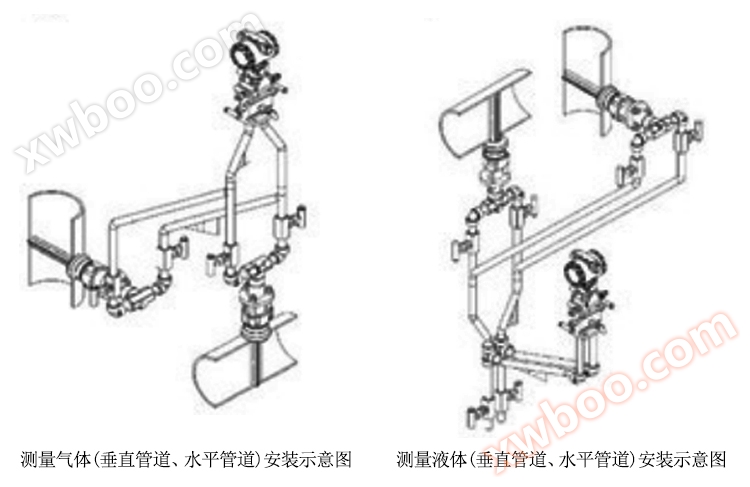
| For vertical pipeline sensors, they can be installed at any position along the 360 degree circumference of the pipeline in the horizontal plane, and the high and low pressure pressure pipes should be in the same plane; When measuring liquids, they should be installed tilted downwards; When measuring gas, it should be installed with an upward tilt. |
| The device for clamping the sensor should ensure no leakage, looseness, or displacement. |
| Due to the fact that the sensor is based on the velocity area method and uses approximate integration theory, it is described using a large number of points. |
|
|
| The distribution equation is established under fully developed velocity distribution conditions. So, in order to obtain an ideal distribution, there must be a certain length of straight pipe section before and after the sensor (see table below) |
| Serial Number |
Installation position of averaging tube flow sensor |
upstream side |
downstream side |
| There is a rectifier |
No rectifier |
| same plane |
Different planes |
|
1 |
There is a 90 ° elbow or tee |
6D |
7D |
9D |
3D |
|
2 |
There are two 90 ° elbows in the same plane |
8D |
9D |
14D |
3D |
|
3 |
There are two 90 ° elbows in different planes |
9D |
19D |
24D |
4D |
|
4 |
Change in pipeline diameter (expansion or contraction) |
8D |
8D |
8D |
3D |
|
5 |
Partially opened gate valves, ball valves, or other throttling devices |
8D |
8D |
8D |
3D |
Note: (1) "D" in the table represents the inner diameter of the pipeline. (2) In the case of insufficient pipeline sections, the upstream should account for 70% of the total pipeline length, and the downstream should account for 30%. At this time, stable readings can still be given, but the accuracy decreases.
|
|
|

|
| Serial Number |
Fault phenomenon |
reason |
Clear plan |
|
1 |
No differential pressure signal output |
1. The high and low pressure valves are not open |
1. Open the high and low pressure valves |
| 2. The balance valve is not tightened |
2. Tighten the balance valve |
|
2 |
Differential pressure signal output too small |
1. There is a leakage phenomenon in the pressure system |
1. Carefully search and eliminate leaks |
| 2. Improper selection of secondary meter range |
2. Reduce the upper limit value of the differential pressure transmitter |
|
3 |
Differential pressure signal output too large |
1. Improper selection of secondary meter range |
1. Increase the upper limit value of the differential pressure transmitter |
| 2. Backpressure hole blockage |
2. Clean the uniform speed tube and eliminate blockages |
|

