
VIP member
Product details
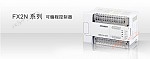
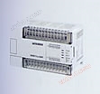
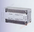
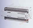
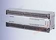
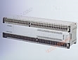
FX2N series PLC

Brief introduction
The FX2n series is the most advanced series in the FX series PLC family. Due to the following characteristics of the FX2n series: maximum compatibility with standard features, faster program execution, comprehensive communication functions, suitability for different power sources in various countries around the world, and a large number of special functional modules to meet individual needs, it can provide maximum flexibility and control capabilities for your factory automation applications.
Special features developed for a large number of practical applications
Developed special functional modules in various fields to meet different needs - analog I/O, high-speed counters.
Positioning control reaches 16 axes, pulse train output or temperature modules have been developed for J and K type thermocouples or Pt sensors.
Up to 8 special functional modules can be configured for each FX2n main unit.
Network and Data Communication
Connect to the world's most popular open networks CC Link, Profibus Dp, and DeviceNet, or use sensor level networks to meet your communication needs.
Other functions
| Built in 24V DC power supply | 24V, 400mA DC power supply can be used for peripheral devices such as sensors or other components. |
| Quickly disconnect the terminal block | Due to the use of excellent maintainability and quick disconnect terminal blocks, the unit can be replaced even if the cable is connected. |
| Clock function and hour meter function | There is a real-time clock standard in all FX2N PLCs. The time setting and comparison instructions are easy to operate. The hour meter function provides valuable information for process tracking and machine maintenance. |
| Continuous scanning function | Define the operation cycle for the continuous scanning time required by the application. |
| Input filter adjustment function | An input filter can be used to flatten the input signal (x000 to x017 in the basic unit). |
| Annotation recording function | Component annotations can be recorded in program registers. |
| Online program editing | Changing programs online will not result in loss of working time or halt of production operations. |
| RUN/STOP switch | The run/stop switch on the panel is easy to operate. |
| remote maintenance | Remote programming software can monitor, upload, or uninstall programs and data through modem communication |
| Password protection | Protect your program with an eight digit password. |
AC power supply, 24V DC input type
| model | Total I/O count | input | output | size Mm (inches) (Width) * (Thickness) * (Height) | |||
|---|---|---|---|---|---|---|---|
| number | type | number | type | ||||
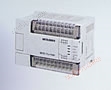 | FX2N-16MR-001 | 16 | 8 | leakage type | 8 | relay | 130*87*90 () |
| FX2N-16MT | transistor | ||||||
 | FX2N-32MR-001 | 32 | 16 | leakage type | 16 | relay | 150*87*90 (5.9*3.4*3.5) |
| FX2N-32MT | transistor | ||||||
 | FX2N-48MR-001 | 48 | 24 | leakage type | 24 | relay | 182*87*90 (7.2*3.4*3.5) |
| FX2N-48MT | transistor | ||||||
 | FX2N-64MR-001 | 64 | 32 | leakage type | 32 | relay | 220*87*90 (8.7*3.0*3.5) |
| FX2N-64MT | transistor | ||||||
 | FX2N-80MR-001 | 80 | 40 | leakage type | 40 | relay | 285*87*90 (11.2*3.4*3.5) |
| FX2N-80MT | transistor | ||||||
 | FX2N-128MR-001 | 128 | 64 | leakage type | 64 | relay | 350*87*90 (13.8*3.4*3.5) |
| FX2N-128MT | transistor | ||||||
FX2N Performance Specifications
| project | Specifications | remark | |
|---|---|---|---|
| Operation control mode | Running through stored program cycles | ||
| I/O control method | Batch processing method (when executing END instruction) | I/O instructions can refresh | |
| Operation processing time | Basic instruction: 0.8 µ s/instruction Application instruction: 1.52 to several hundred µ s/instruction | ||
| programming language | Logic ladder diagram and instruction list | Using a step ladder diagram can generate SFC type programs | |
| Program capacity | Built in 8000 steps | Additional storage boxes can be used to expand up to 16000 steps | |
| Number of instructions | Basic sequence instruction: 27 Step ladder instruction: 2 Application instruction: 128 | Maximum available 298 application instructions | |
| I/O configuration | The maximum hardware I/O configuration point is 256, depending on the user's choice (maximum software can set address input to 256, output to 256) | ||
| Auxiliary relay (M coil) | average | 500 points | M0 to M499 |
| lock | 2572 points | M500 to M3071 | |
| special | 256 points | M8000 to M8255 | |
| Status relay (S coil) | average | 490 points | S0 to S499 |
| lock | 400 points | S500 to S899 | |
| initial | ten o'clock | S0 to S9 | |
| Signal alarm | 100 points | S900 to S999 | |
| Timer (T) | 100 milliseconds | Range: 0 to 3276.7 seconds 200 points | T0 to T199 |
| 10 milliseconds | Range: 0 to 327.67 seconds 46 points | T200 to T245 | |
| 1 millisecond hold type | Range: 0 to 32.767 seconds 4 o'clock | T246 to T249 | |
| 100 milliseconds | Range: 0 to 3276.7 seconds 6 o'clock | T250 to T255 | |
| Counter (C) | Generally 16 digits | Range: 0 to 32767, 200 points | C0 to C199 Type: 16 bit up counter |
| Lock 16 bits | 100 points (subsystem) | C100 to C199 Type: 16 bit up counter | |
| Generally 32-bit | three p.m. | C200 to C219 Type: 16 bit up/down counter | |
| Lock 32-bit | three p.m. | C220 to C234 Type: 16 bit up/down counter | |
| High-speed counter (C) | single-phase | Range: -2147483648 to+2147483647 numbers General rule: Choose a counter combination with a counting frequency not exceeding 20KHz Pay attention to all counter locks | C235 to C240 6 o'clock |
| Starting from single-phase c/w Stop input | C241 to C245 5 o'clock | ||
| bipolar | C246 to C250 5 o'clock | ||
| A/B phase | C251 to C255 5 o'clock | ||
| Data register (D) | average | 200 points | D0 to D199 Type: 16 bit data storage register pair for 32-bit components |
| lock | 7800 points | D200 to D7999 Type: 16 bit data storage register pair for 32-bit components | |
| File register | 7000 points | D1000 to D7999 parameter settings through 14 block 500 program steps Type: 16 bit data storage register | |
| special | 256 points | From D8000 to D8255 Type: 16 bit data storage register | |
| Address change | four p.m. | V0 to V7 and Z0 to Z7 Type: 16 bit data storage register | |
| indicator (P) | Used for CALL | 128 points | P0 to P127 |
| Used for interrupting | 6 input points, 3 timers, 6 counters | 100 * to 150 * and 16 * to 18 ** (Rising trigger *=1, falling trigger *=0, * *=time (unit: milliseconds)) | |
| Nested hierarchy | Used for MC and MRC at 8 o'clock | N0至N7 | |
| constant | Decimal K | 16 bits: -32768 to+32768 32-bit: -2147483648 to+2147483647 | |
| Hexadecimal H | 16 bits: 0000 to FFFF 32-bit: up to FFFFFFFF | ||
| floating point | 32-bit: ± 1.175 * 10-38, ±3.403*10-38(Cannot be directly inputted) | ||
Online inquiry
-
Contacts
-
Company
-
Telephone
-
Email
-
WeChat
-
Verification Code
-
Message Content
-