
VIP member
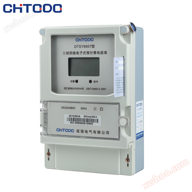
DTSY6607 State Grid Three phase Electronic Prepaid Energy Meter
Main features: Application of computer management, purchasing electricity first and then using it; The maximum operating power can be limited within t
Product details
1. purpose.Characteristics and scope of adaptation
DTSY6607Our company uses imported specialized large-scale integrated circuits with 16 bits for the series of plug-in three-phase electronic prepaid energy metersA/DConversion, digital multiplier, application of digital sampling processing technology, and data acquisition, processing, storage, and application by advanced microcontroller processing systemsSMTA new type of instrument for process manufacturing. Suitable for measuring rated frequencies of50Hzperhaps60HzThe consumption of active electrical energy in a three-phase three wire or three-phase four wire AC power grid. The product complies withGB/T17215.321-2008《1Level and2Static AC Active Energy Meter andGB/T 18460.3-2001《ICCard prepaid electricity sales system3Part: All technical requirements for prepaid energy meters.
Main features: Application of computer management,Purchase electricity first and then use itWithin the rated current range, the maximum operating power can be limited (by the power supply department); One meter, one card, dedicated card, no power loss after card loss, can be used after card replacement; Electric cards can transmit data bidirectionally and automatically power off to alert users when purchasing electricity; When the battery level is zero, the power will automatically trip and cut off; And it has certain anti-theft software design, etc.
This table is designed for fixed installation indoors and is suitable for environments with temperatures not exceeding-20~+55℃, relative humidity not exceeding85%And the air does not contain corrosive gases and should avoid the influence of dust, mold, insects, etc.
2.Specifications, models, and technical indicators
2.1Specification and model
|
model |
accuracy class level |
reference voltage Un |
Rated current Ib |
Access method |
instrument constant imp/kWh |
|
DTSY6607 DSSY6607 |
1perhaps2 |
3X220/380 3X57.9/100 |
1.5(6) |
Mutual inductance type |
1600 |
|
5(20) |
direct-type |
800 |
|||
|
10(40) |
direct-type |
400 |
|||
|
15(60) |
direct-type |
400 |
|||
|
20(80) |
direct-type |
400 |
2.2Basic Error (Balance Load Error Limit)
|
current |
Power factor (COSφ) |
Basic error(%) |
||
|
Directly connect the instrument panel |
Transformer instrument |
1 |
2 |
|
|
0.05Ib≦I<0.1Ib |
0.02Ib≦I<0.05In |
1 |
±1.5 |
±2.5 |
|
0.1Ib≦I<>< span=""><> |
0.05In≦I<>< span=""><> |
1 |
±1.0 |
±2.0 |
|
0.1Ib≦I<0.2Ib |
0.05In≦I<0.1In |
0.5(Sensory) 0.8(Capacity) |
±1.5 |
±2.5 |
|
0.2Ib≦I<>< span=""><> |
0.1In≦I<>< span=""><> |
0.5(Sensory) 0.8(Capacity) |
±1.0 |
±2.0 |
Note: (IbRated currentImaxMaximum current
2.3start
At reference voltage, reference frequency, andCOSφ=1.0Under the condition of, the load current is0.004Ib(1level)、0.005Ib(2level)The instrument should be able to continuously measure electricity.
2.4shunt running
Voltage circuit with rated voltage115%When there is no current in the current circuit, the test output of the instrument should not generate more than one pulse.
2.5Voltage range
Normal operating voltage:0.9Un-1.1Un
Maximum operating voltage:0.8Un-1.15Un
2.6power consumption
Voltage line power consumption: ≤2Wand10VA
Current line power consumption: ≤4.0VA
3.Working principle
3.1Working principle block diagram
The electric energy meter obtains voltage sampling signals from the voltage divider, current sampling signals from the current transformer, voltage current product signals from the multiplier, and then generates a counting pulse with frequency proportional to the product of voltage and current through frequency conversion.
3.2data processing
Electric energy metering pulses are sent through a photoelectric couplerCPUProcessed and stored in non-volatile storage after computationEEPROMIn the middle. Managed by a computer information system, throughICCard reader/writer, capable of writing a certain amount of power and monitoring requirementsICThe microprocessor system in the card input table, throughCPUAfter calculation, provide display, alarm, and cut-off status signals.
4.Installment and use
4.1 The electric energy meter can be installed and used after passing the inspection and being sealed with a lead seal before leaving the factory. Electric energy meters without lead seals or stored for too long should be re inspected by relevant departments before installation and use.
4.2The electric energy meter should be installed in a ventilated and dry indoor area, and can be installed at any position, but it is usually installed vertically. It is recommended to install it at a height of1.8About meters, install electrical energy
The bottom plate of the watch should be fixed on a sturdy, fire-resistant, and vibration resistant wall.
4.3In places with pollution and potential damage to the structure, the energy meter should be installed in a protective cabinet.
4.4When installing wiring, follow the wiring diagram on the terminal cover of the electric energy meter or the corresponding wiring diagram in this manual. It is best to use copper connectors to prevent the electric energy meter from burning out due to poor contact.
4.5When using an electric energy meter in areas with frequent lightning strikes, lightning protection measures should be taken to avoid damaging the meter due to lightning strikes.
4.6The load capacity of an electric energy meter is0.05Ib~Imax(Direct access type) or0.02Ib~ImaxExceeding this load capacity between (connected through transformers) will result in inaccurate measurement of the energy meter or burning of the current coil due to heating.
4.7The reading of an electric energy meter connected through a transformer must be multiplied by the transformation ratio to obtain the actual amount of electricity.
4.8One table, one card: held by the userICCards cannot be exchanged, and in case of loss, a replacement card should be purchased from the power supply department (i.e. the electricity sales office).
4.9Preparation for purchasing electricity: Users mustICInsert the card into the card slot once to facilitate sending the data in the table back to the computer database.
4.10Electricity purchase method: When selling electricity, theICCard insertionICCard reader/writer, simultaneously operating the computer to encrypt and write user ID, pre ordered power, capacity limit method, and power limit, etcICCard.
4.11Electricity card usage: Insert the power purchase card into the card slot. If it is a valid power purchase card, the electricity meter will automatically read the data into the meter,LCD(LED)The display screen sequentially shows: purchased electricity quantity(P0== XXXX)Total purchased electricity(P=XX XXXX)Number of electricity purchases(PC== XXXX)Alarm power level(P1==XXXX)Credit limit(P2== XXXX)Capacity limiting power(F0X= XX:XX)Please store the unplugged card properly.
4.12Operation display: During the operation of the energy meter, the display screen alternately shows the remaining power and total power consumption in the meter.
4.13Overcapacity alarm: During the operation of the energy meter, if the "alarm indicator light" flashes rapidly, it warns the user that the electricity has been used beyond capacity; If the user is set to the over capacity power-off limit mode, then the over capacity electricity will be used30In seconds, the brake will be pulled3Minutes and displayed in countdown mode(180Restore power supply in seconds; If the user inserts the card and responds, the power supply can be immediately restored.
4.14Accumulation limit: If purchasing electricity+Remaining power>Accumulated power(10000kWh)If the purchased power is not read in, the display will show a "remaining limit" prompt, and the power in the card will still be valid.
4.15Warning reminder: When the remaining battery level in the meter is less than the "alarm battery level"2When doubled, the 'alarm indicator light' will flash (with intervals of)1Display a reminder to the user to purchase electricity in seconds. If the user responds by inserting a card, the "alarm indicator light" will flash at intervals of2Seconds can avoid power outage warnings.
4.16Power outage warning: If the user does not insert the card in response to the warning reminder and sets an over capacity alarm, the remaining battery level will be the alarm battery level agreed upon by the user (or the current purchased battery level)10%)At this time, the energy meter will trigger a power outage warning and display a "power off" promptICSimply plug it into the card slot once to restore power supply. If this table cannot be found after pulling the switchICCard, can be borrowed from neighborsICInsert the card to restore power supply.
4.17Power purchase reminder: When the remaining power in the meter is less than the "alarm power", the "alarm indicator light" will remain on as a constant reminder.
4.18Fault declaration: When the remaining power is displayed as zero or negative, a "trip" prompt will be displayed. If the energy meter continues to operate, the user should immediately purchase electricity and proactively report the situation to the power supply bureau.
5.External dimensions

6.Functional terminal wiring


8. Transportation and Storage
8.1 The transportation and unpacking of electric energy meters should not be subjected to severe impacts, and should be carried out according toGB/15464-1995The General Technical Conditions for Instrument Packaging stipulate transportation and storage.
8.2 The electric energy meter should be stored in its original packaging box at an ambient temperature of-30℃~+65℃, relative humidity not exceeding85%And there should be no gas in the air that can cause corrosion, and the ambient temperature should not change dramatically.
8.3The electric energy meter should be placed on the rack in its original packaging condition, with a stacking height of no more than five boxes. After unpacking, the stacking height of a single packaged electric energy meter should not exceed five boxes, with an inner packaging(plastic bag)The unsealed energy meter should not be stored.
9. Warranty period
From the date of manufacture of the electric energy meter18Within one month, if the user fully complies with the requirements specified in this manual and finds that the electric energy meter does not meet the technical requirements specified in the product standard while the manufacturer's lead seal is still intact, or if there is a certificate from the power and metering department, the manufacturer will provide free repair or replacement.
Online inquiry
-
Contacts
-
Company
-
Telephone
-
Email
-
WeChat
-
Verification Code
-
Message Content
-