
VIP member
CS screw lift
Customers who have product requirements for CS elevators, CS screw elevators, and CS spiral elevators are welcome to consult and purchase from our com
Product details
Detailed introduction of CS screw lift
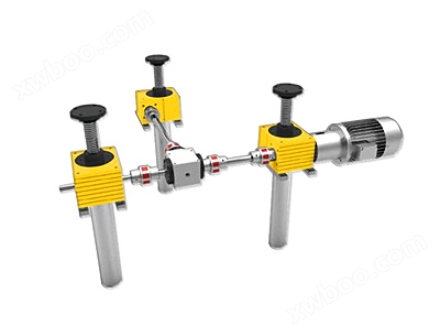
CS screw liftIt is a motion unit composed of a worm gear reducer and a screw nut pair cleverly combined together. It can be used alone or combined quickly through connectors like building blocks to achieve movements such as lifting, reciprocating, flipping, etc. of objects. The CS series square screw elevator adopts a novel square shell, which makes its structure compact, small in volume, light in weight, and easy and flexible to install. It can be installed on all sides, with various installation methods. When multiple units are used, the position is compact, neat, and beautiful. There are two types of square shell materials: aluminum alloy and cast iron (aluminum alloy materials are generally selected for specifications below 25KN, but can also be customized according to user requirements).

 Technical parameters:

CS screw liftAs a functional component, it has been widely used in various industries. For example, transmission devices and CNC actuators in the mechanical industry; Roll motion devices in the metallurgical industry, ladle lifting and flipping devices in steel mills, and motion transmission devices in places beyond human reach; Vehicle lifting frames, large flexible clamping, indexing fixtures, welding robots, etc. in the railway vehicle industry; Lifting devices in the construction industry, automatic or remote opening devices for large doors and windows, and so on.
CS square worm gear screw elevator form and specification representation
Body specifications
Divided into 9 types: CS2.5-CS500, with lifting forces ranging from 2.5KN to 500KN.
gear ratio
N-type - ordinary speed ratio;
L-type - slow speed ratio.
structural style
Type A - The screw moves axially without rotating;
Type B - The nut moves axially and the screw rotates.
Spiral elevator screw joint type
The screw head part of the A-type structural form is divided into five types: Type 1 (cylindrical), Type 2 (flange), Type 3 (threaded), Type 4 (flat head), and Type 5 (open);
There are two types of screw heads in the B-type structural form: Type 1 (cylindrical) and Type 0 (without joints).
Additional requirements (optional)
There are three additional requirements for the A-type structural form: ball screw type (B), with anti rotation device (P), and with protective cover (S);
The additional requirements for the B-type structural form include two types: ball screw type (B) and with protective cover (S).
CS series screw lift model representation method:
| CS2.5 | CS5 | CS10 | CS25 | CS50 | CS150 | CS250 | CS350 | CS500 | |
| lead screw | Tr14×4 | Tr18×4 | Tr20×4 | Tr30×6 | Tr40×7 | Tr60×9 | Tr80×10 | Tr100×10 | Tr120×14 |
| A | 20 | 20 | 30 | 30 | 45 | 55 | 55 | 65 | 90 |
| B | 77 | 97(110) | 120(124) | 132 | 182 | 255 | 275 | 360 | 466 |
| C | 25 | 31 | 37.5 | 41 | 58.5 | 80 | 82.5 | 110 | 133 |
| D | 60 | 80 | 100 | 130 | 180 | 200 | 240 | 290 | 360 |
| E | 48 | 60 | 78 | 106 | 150 | 166 | 190 | 230 | 290 |
| F | 50 | 72 | 85 | 105 | 145 | 165 | 220 | 250 | 300 |
| G | 38 | 52 | 63 | 81 | 115 | 131 | 170 | 190 | 230 |
| H | M6 | M8 | M8 | M10 | M12 | M20 | M30 | M36 | M42 |
| ΦJk6 | 9 | 10 | 14 | 16 | 20 | 25 | 30 | 35 | 48 |
| K1 | 20 | 25 | 32 | 45 | 63 | 71 | 80 | 100 | 135 |
| K2 | 16 | 21 | 29 | 42 | 63 | 66 | 75 | 95 | 115 |
| L | 22 | 31 | 40 | 54 | 78 | 83 | 100 | 125 | 150 |
| L1 | 20 | 22.5 | 25.5 | 43 | 45 | 65 | 65 | 63 | 97.5 |
| L2 | 12 | 13 | 15 | 15 | 16 | 30 | 45 | 54 | 80 |
| N | 92 | 120 | 140 | 195 | 240 | 300 | 355 | 380 | 500 |
| P | 62 | 74(87) | 93(97) | 105 | 149 | 200 | 205 | 270 | 326 |
| Q | 3×3×14 | 3×3×18 | 5×5×20 | 5×5×36 | 6×6×36 | 8×7×56 | 8×7×56 | 10×8×56 | 14×9×90 |
| T | 12 | 12(25) | 18(22) | 23 | 32 | 40 | 40 | 50 | 60 |
| ΦU | 28 | 32 | 40 | 50 | 65 | 90 | 125 | 150 | 180 |
| ΦW | 26 | 30(48) | 40(57) | 46 | 70 | 85 | 120 | 145 | 170 |
| Y | 50 | 62 | 75 | 82 | 117 | 160 | 165 | 220 | 266 |
| Z | 24 | 32.5 | 35 | 44 | 55 | 70 | - | - | - |
| Z1 | M6 | M8 | M8 | M8 | M10 | M10 | - | - | - |
| Z2 | 6 | 10 | 12 | 12 | 15 | 15 | - | - | - |
| Screw joint type 1 | |||||||||
| Φak6 | 8 | 12 | 15 | 20 | 25 | 40 | 60 | 80 | 95 |
| b | 12 | 15 | 20 | 25 | 30 | 45 | 75 | 100 | 120 |
| c | 15 | 20 | 25 | 30 | 35 | 55 | 90 | 115 | 140 |
| Screw joint type 2 | |||||||||
| Φd | 50 | 65 | 80 | 90 | 110 | 150 | 220 | 260 | 310 |
| Φe | 40 | 48 | 60 | 67 | 85 | 117 | 170 | 205 | 240 |
| Φf | 4×Φ7 | 4×Φ9 | 4×Φ11 | 4×Φ11 | 4×Φ13 | 4×Φ17 | 4×Φ25 | 4×Φ32 | 4×Φ38 |
| g | 19 | 24 | 28 | 28 | 34 | 57 | 72 | 92 | 142 |
| s | 16 | 20 | 21 | 23 | 30 | 50 | 60 | 80 | 120 |
| r | 6 | 7 | 8 | 10 | 15 | 20 | 30 | 40 | 40 |
| Φx | 26 | 30 | 40 | 46 | 70 | 85 | 120 | 145 | 170 |
| Screw joint type 3 | |||||||||
| h | 12 | 19 | 20 | 22 | 29 | 48 | 58 | 78 | 118 |
| i | M8 | M12 | M14 | M20 | M30 | M36 | M64×3 | M72×3 | M100×3 |
| k | 15 | 23 | 25 | 27 | 35 | 55 | 70 | 90 | 140 |
| Screw joint type 4 | |||||||||
| l h10 | 12 | 15 | 20 | 30 | 35 | 40 | 80 | 110 | 120 |
| m | 40 | 55 | 63 | 78 | 100 | 130 | 155 | 220 | 330 |
| n | 20 | 30 | 36 | 45 | 60 | 66 | 110 | 170 | 230 |
| Φo H8 | 8 | 10 | 12 | 16 | 20 | 22 | 60 | 80 | 90 |
| p1 | 33 | 44 | 52 | 58 | 74 | 104 | 117 | 147 | 222 |
| Φu | 25 | 30 | 40 | 45 | 60 | 85 | 120 | 160 | 170 |
| v | 10 | 15 | 18 | 25 | 30 | 33 | 50 | 85 | 130 |
| v1 | 30 | 40 | 45 | 53 | 70 | 97 | 105 | 135 | 200 |
| Screw joint type 5 | |||||||||
| l H10 | 8 | 12 | 14 | 20 | 30 | 36 | —— | —— | —— |
| m | 42 | 61 | 72 | 105 | 160 | 188 | —— | —— | —— |
| n | 26 | 37 | 44 | 65 | 100 | 116 | —— | —— | —— |
| Φo H8 | 8 | 12 | 14 | 20 | 30 | 35 | —— | —— | —— |
| p1 | 35 | 52 | 63.5 | 85 | 124 | 151 | —— | —— | —— |
| u | 16 | 24 | 27 | 40 | 60 | 70 | —— | —— | —— |
| Φu1 | 14 | 20 | 24.5 | 34 | 52 | 60 | —— | —— | —— |
| v | 16 | 24 | 28 | 40 | 60 | 72 | —— | —— | —— |
| v1 | 32 | 48 | 56 | 80 | 120 | 144 | —— | —— | —— |
Technical parameters:
| CS2.5 | CS5 | CS10 | CS25 | CS50 | CS150 | CS250 | CS350 | CS500 | |
| lead screw | Tr14×4 | Tr18×4 | Tr20×4 | Tr30×6 | Tr40×7 | Tr60×9 | Tr80×10 | Tr100×10 | Tr120×14 |
| C | 25 | 31 | 37.5 | 41 | 58.5 | 80 | 82.5 | 110 | 133 |
| D | 60 | 80 | 100 | 130 | 180 | 200 | 240 | 290 | 360 |
| E | 48 | 60 | 78 | 106 | 150 | 166 | 190 | 230 | 290 |
| F | 50 | 72 | 85 | 105 | 145 | 165 | 220 | 250 | 300 |
| G | 38 | 52 | 63 | 81 | 115 | 131 | 170 | 190 | 230 |
| H | M6 | M8 | M8 | M10 | M12 | M20 | M30 | M36 | M42 |
| ΦJk6 | 9 | 10 | 14 | 16 | 20 | 25 | 30 | 35 | 48 |
| K1 | 20 | 25 | 32 | 45 | 63 | 71 | 80 | 100 | 135 |
| K2 | 16 | 21 | 29 | 42 | 63 | 66 | 75 | 95 | 115 |
| L | 22 | 31 | 40 | 54 | 78 | 83 | 100 | 125 | 150 |
| L1 | 20 | 22.5 | 22.5 | 43 | 45 | 65 | 65 | 63 | 97.5 |
| L2 | 12 | 13 | 15 | 15 | 16 | 30 | 45 | 54 | 80 |
| N | 92 | 120 | 140 | 195 | 240 | 300 | 355 | 380 | 500 |
| NL | Lift+60 | Lift+68 | Lift+74 | Lift+86 | Lift+123 | Lift+149 | Lift+160 | Lift+180 | Lift+220 |
| P | 62 | 74 | 93 | 105 | 149 | 200 | 205 | 270 | 326 |
| Q | 3×3×14 | 3×3×18 | 5×5×20 | 5×5×36 | 6×6×36 | 8×7×56 | 8×7×56 | 10×8×56 | 14×9×90 |
| T | 12 | 12 | 18 | 23 | 32 | 40 | 40 | 50 | 60 |
| ΦW | 26 | 30 | 40 | 46 | 70 | 85 | 120 | 145 | 170 |
| Margin X | 10 | 12 | 15 | 20 | 25 | 25 | 25 | 25 | 30 |
| Y | 50 | 62 | 75 | 82 | 117 | 160 | 165 | 220 | 266 |
| Z | 24 | 32.5 | 35 | 44 | 55 | 70 | - | - | - |
| Z1 | M6 | M8 | M8 | M8 | M10 | M10 | - | - | - |
| Z2 | 6 | 10 | 12 | 12 | 15 | 15 | - | - | - |
| Sports Nut | |||||||||
| a | 40 | 44 | 44 | 46 | 73 | 99 | 110 | 130 | 160 |
| b | 10 | 12 | 12 | 14 | 16 | 20 | 30 | 35 | 40 |
| Φch9 | 24 | 28 | 32 | 42 | 63 | 85 | 105 | 130 | 160 |
| Φd | 44 | 48 | 55 | 66 | 95 | 125 | 190 | 240 | 300 |
| Φe | 34 | 38 | 45 | 54 | 78 | 105 | 150 | 185 | 230 |
| Φf | 5 | 6 | 7 | 7 | 9 | 11 | 17 | 25 | 28 |
| Screw joint type 1 | |||||||||
| h | 12 | 15 | 20 | 25 | 30 | 45 | 75 | 100 | 120 |
| Φik6 | 8 | 12 | 15 | 20 | 25 | 40 | 60 | 80 | 95 |
Online inquiry
-
Contacts
-
Company
-
Telephone
-
Email
-
WeChat
-
Verification Code
-
Message Content
-